# Basic Assemblies
Defining relationships between multiple parts to create assemblies is a key part of parametric modelling for engineering. You can define position and motion relationships — called joints to create working assemblies for demos and basic testing. When creating assemblies in Fusion, it helps to think about the CAD geometry as real parts coming together in the world. There are a number of different types of joints and you should leverage all of them to create useful assemblies. We'll review a few more common ones below.
# Rigid Joints
These are the simplest joints and generally used for things like fasteners, press-fit parts, and any components that should be fixed to one another.
# Cylindrical Joints
Gas springs, slide pins, and other cylindrical objects can be represented with this joint.
# Slot Joint
This joint constrains a pin in a slot. Keep in mind that this doesn't actually follow the slot in the model, it just moves along the axis chosen in the dialog. Also note how limits were set on this joint, giving it the appearance of the pin following the slot. In general, joints don't actually make use of solid interferences as that requires a lot of computing power (Fusion can do those computations, but we'll get into that later). Joints use geometric definitions like edges and points, along with rules about how to move.
# Ball Joint
This joint creates a spherical relationship between two points. It makes the most sense to use spherical geometry, but the relationship is really just two points and some rules.
# Assignment
Various CAD software treats the assembly process differently, but for this exercise, you'll make use of a workflow in Fusion that is also found in Solidworks and Creo (fka Pro/Engineer). Create a new file in your table folder, then insert your table and tableware. Use the dining table version and set places for 4-8 people depending on its size. Copy and paste multiple instances of the same part.
# Insert Parts
Insert each part from the file manager.
# Joint Origins
Fusion derives points and edges to create joints from existing geometry. Generally this works well, but sometimes you need to create a deliberate location for a joint, like on the foot of this plate. You can define a joint origin on a part, and then later use that to create a relationship where one wouldn't conveniently be derived from the geometry in the file.
Here, we make use of the sketch used to create the plate revolve to define the location of the joint origin. Note the option to reorient it by defining Z and X axes.
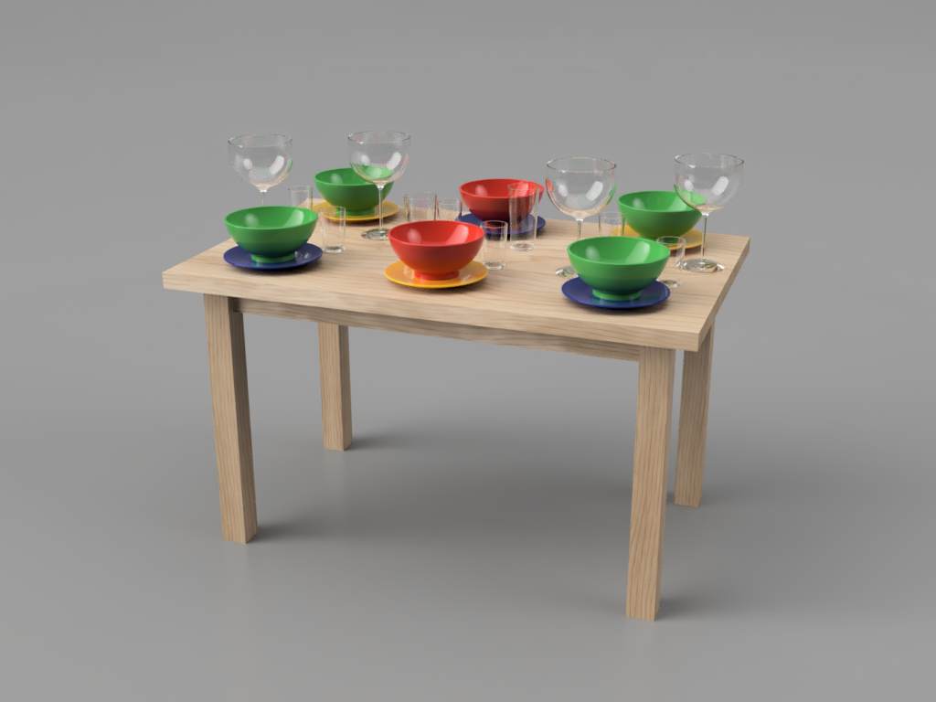
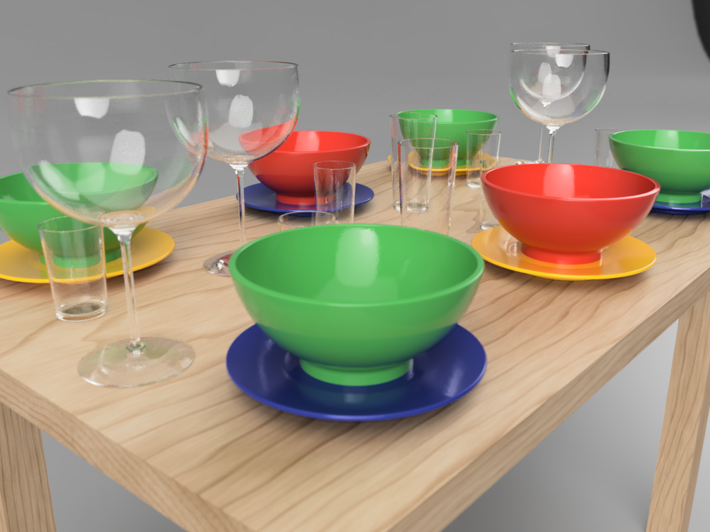
# Set the Table
Once you have your parts in and any joint origins defined, create a setting for 4-8 people using various joints.
TIP
Note that this example required updating the plate after inserting the joint origin. You will have to do this whenever you make a change to a part that is inserted into another part.
# Render the table