# Basic Flashlight
# Bringing it all together
You've been working with sketches, extrudes, and revolves so far. This exercise brings those skills together to make something a bit more complicated — a flashlight. This flashlight will be a fairly simple design, consisting of an injection molded handle, screw-on head with lens, and slide switch. Models are often built iteratively, moving back and forth in the timeline to control features. It won't have detailed internals, like batteries or electronic components. It will also forgo the threading to attach the head to the handle. Think of this model as a first pass at a design.
# Handle Body
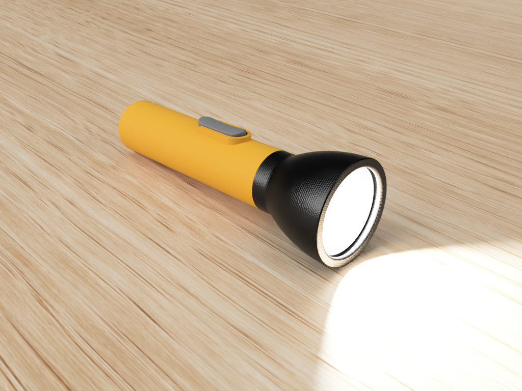
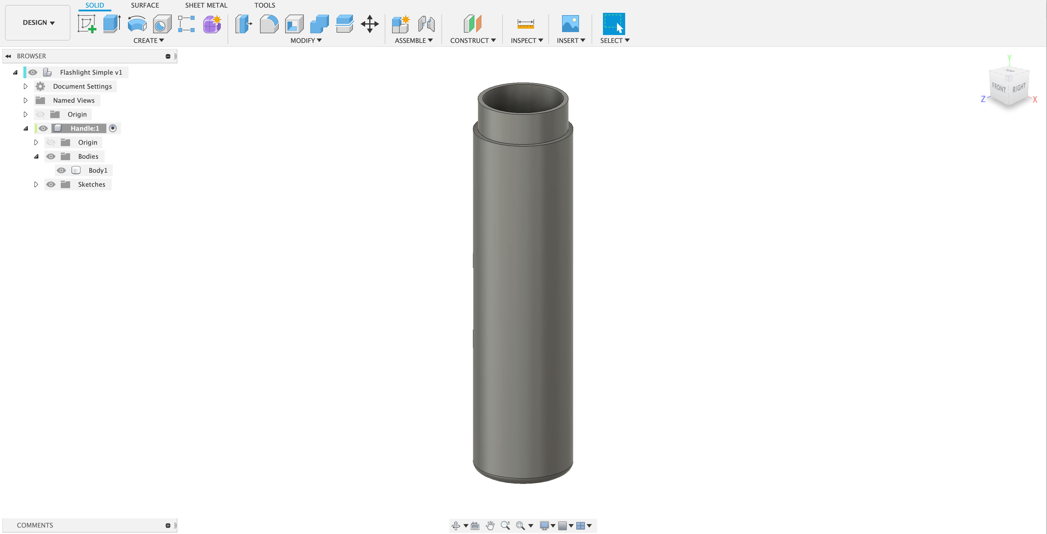
Start by creating a component that will become the flashlight handle. In it, extrude a cylinder from the top plane. Add a fillet to the bottom edge.
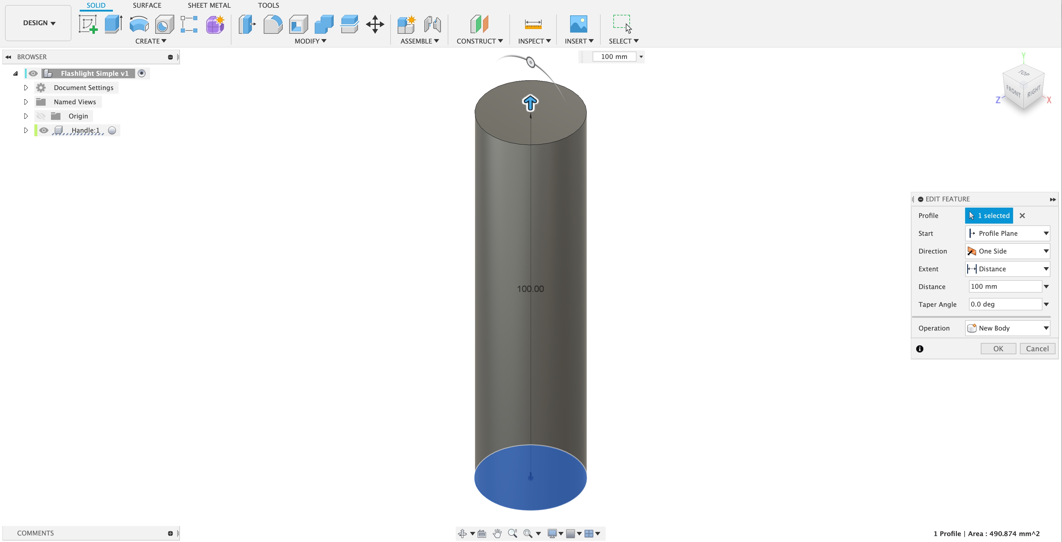
Use a shell feature to hollow the handle body. It's important to shell the body after creating the fillet so it is incorporated into the wall thickness.
While the threads between the head and handle won't be added at this phase, it's a good idea to create placeholder geometry for these types of features when you can. Here, the handle will be cut back to provide a better surface for adding threads later on.
Start with a sketch to define the eventual cut. Note the use of a construction line and a point to establish a circle midway between the inner and outer edges of the handle wall, assuring that the cut will always be half the wall thickness.
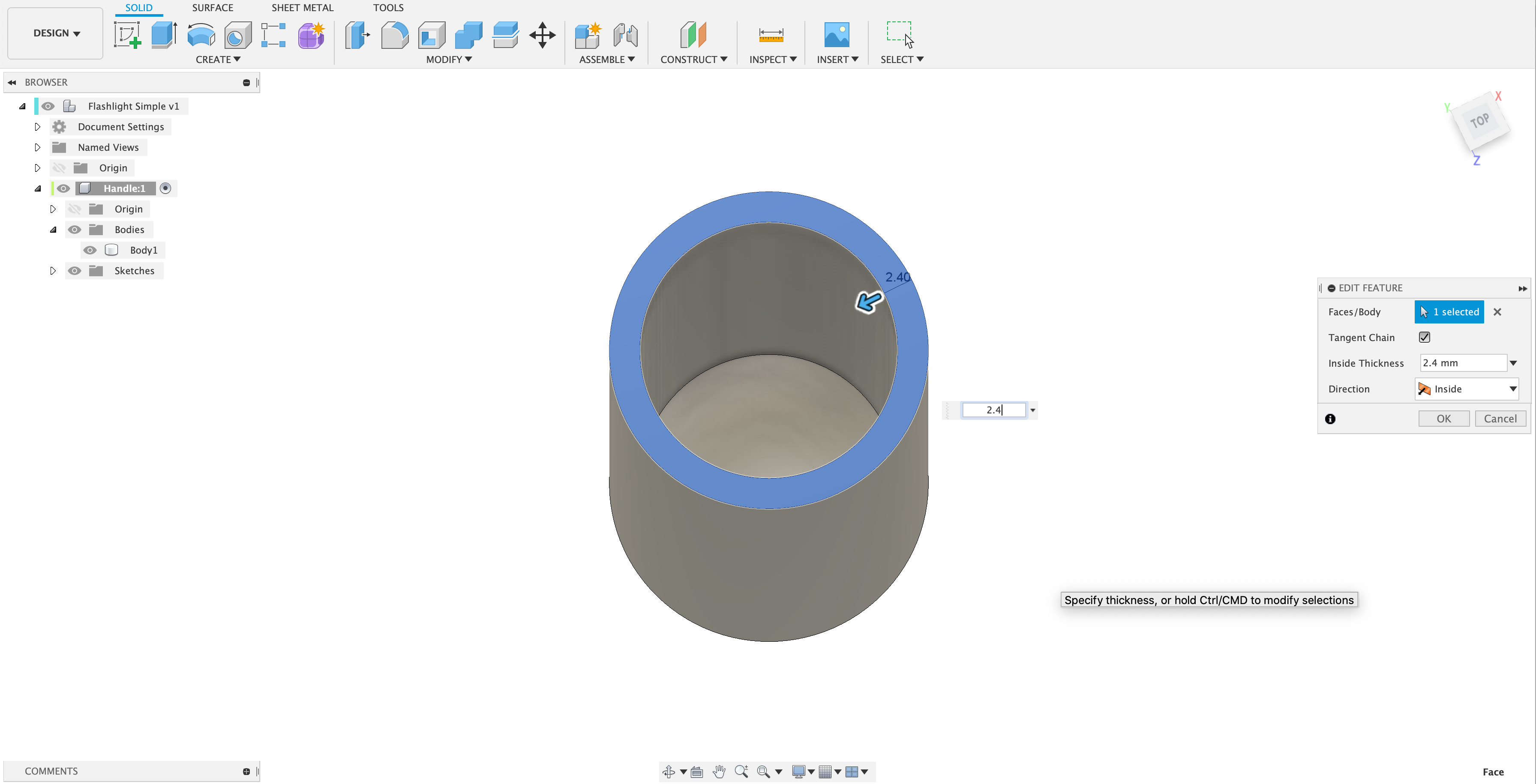
All solid features — extrudes and revolves, as well as sweeps and lofts which you'll learn about later — can be used to create as well as remove geometry. Note the Operation dropdown in the extrude settings, which here is set to Cut.
The finished cut.
# Head Revolve
Making the head of the flashlight is a straightforward revolve. Start with a new component to help organize the file, then create a profile on the front plane to define the profile. Aligning the sketch in this new component to the handle is key. To be explicit about which parts of the handle get used to define the sketch, you can pull existing geometry into a sketch, either by projecting it to the sketch plane, or finding any intersections the plane has with existing geometry. It is good practice to define geometry explicitly, rather than let the sketch tools imply what edges and points are pulled in. Projected / intersected geometry is parametric — if the geometry changes, so does the projected curves and edges.
# Switch
The switch is the most complex part of this flashlight model, making use of multiple features and aligning to the handle. By combining features, you can create complex geometry from simple sketches, which makes later edits within the timeline possible.
# Switch Slot
Providing a slot in the handle of the flashlight allows you to locate the switch in later features, as well as begin defining its mechanical operation. This switch will slide up and down to turn the flashlight on and off, so a simple slot in one side of the handle is enough to get the design started. Remember, it can always be updated later.
Edit the handle component and begin a sketch on the front plane. use the slot sketch tool to easily create a slot outline. Cut through one side of the handle using the extruded cut feature.
# Switch Hood
In this design, the switch will have a hood protruding from the side of the handle, with a flat face. To create this and maintain editablilty the best option is to first define a tangent plane to the side of the handle, then define an offset plan from that to establish the protrusion distance. On that plane, create an inverted 'U' that sits just outside the slot you made in the previous step.
WARNING
Projecting geometry can sometimes have unexpected results.
Note in the video below that a curve projected directly from the top edge of the switch slot cannot be set concentric to an arc in the hood layout sketch. In this case, the 3-dimensional edge created when the slot was cut into the cylindrical handle cannot be cleanly flattened into an arc again. In cases like this, project the original sketch used to create the cut. It is 2-dimensional and Fusion has no trouble projecting it as an arc.
Extrude features in Fusion do not just have to be to a depth, or even end with a planar surface. In most cases, you can extrude a profile to an curved surface and Fusion will sort out how to merge the geometry.
WARNING
Extruding to existing geometry has limits. The profile being extruded must intersect the existing surfaces and solids, and very complex surfaces can cause the option to fail.
EXPERIMENT
Select different termination surfaces to see how extruding to an object works.
# Complex Forms
The switch needs to fit into the opening you created for the slot, as well as the hood, while also matching the cylindrical surfaces of the handle body. The contact surface pushed against to slide the switch curves in 2 directions. This shape cannot be created with an extrude or a revolve alone. An extrude cannot create the compound-curved contact surface. A revolve will create the curved surfaces — including the compound curved contact surface — but will not end with the overall shape to match the slot and hood.
The solution is to use both revolve and extrude operations to create this complex form. This example also incorporates fillet and chamfer features as well. When planning forms like this, it helps to think about them in 2-dimensional profiles. Imagine this form as front and side elevation drawings. Feel free to sketch those yourself on paper if it helps to work through the form. If you were designing a part like this, such profile sketches would be a common way to work through the form.
# Switch Profile
First, create a new component for the switch.
Start with the revolved feature. Imagine the side view and, on the right plane, create the revolve profile sketch. Note the use of projected and intersected geometry from the handle to align the sketch. Also note that this sketch just creates the outer and inner blocks of the switch. It is much simpler to create the slot tab later on.
# Switch Revolve
Now revolve the profile sketch. You can revolve multiple closed profiles just like extrudes. The resulting ring shape will look strange, but don't worry. We'll trim it back in the next step.
# Switch Extrude
Now, think about the front view of the switch. It should sit within the hood, and the bottom edge should also be rounded to match the design. Use a sketch on the front plane to capture this outline. It doesn't matter that the front plant doesn't actually touch the existing revolve. Again, project geometry from the handle to help define and align the front view profile.
Note the use of the initial hood sketch and not the hood edges to avoid a projection error. This may or may not be necessary depending on the design, but is a good practice as it gets back to the earliest and cleanest design intent. Whether or not you use it here, this technique is a good one to keep in your back pocket should a projection from an edge not work as expected.
Once the profile is extruded, note the Intersect option used. This is an incredibly powerful variant on the Cut option, removing all geometry outside the sketch profile.
# Switch Slide Extrude
The two revolved, cut forms need to be connected so they can slide up and down within the handle slot. Note the use of the original slot profile sketch, but that a bottom curve is drawn from the midpoint. This is planning ahead for the mechanical relationship between the parts. If the extrude is the same length as the slot, the switch will not be able to slide anywhere.
An extrude will be used to create the switch slide, but both start and end objects will be defined. Note that the sketch is on the front plane even though the extrude does not actually start there. While you could create a tangent plane for such an operation, it is unnecessary. When you specify a starting object for an extrude, that profile is essentially projected onto the surface as part of the operation.
Setting this extrude to Join attaches the 2 switch parts, creating one unified switch part.