# Parametric Sketching
Sketching is a key skill for all modeling, but it is especially important in parametric modeling. Sketching might be something of a misnomer here — CAD sketches are incredibly precise and, if done properly, well defined entities. Sketches in CAD are the points, lines, and curves that help define solids and surface geometry down the road.
# Core Concepts
Sketches can be thought of as the foundation for further geometry (surfaces and solids) are later built. They define location, dimensions, and overall shape of later features. The sketching tools in most parametric modelers are incredibly powerful, and enable you to create not just complex shapes but actual design systems — you can build adjustments and controls that enable later adjustments or configuration.
Some key details of sketches:
- World Space: In order to create a model, it needs to be located in space. All modeling software provides some notion of an origin, which can be thought of as the center of the imagined 3D universe.
- Plane: Sketches are almost always 2-dimensional entities (we'll cover exceptions later). Defining a plane is the starting point in locating the sketch in the 3D world. Every sketch plane will also provide a sketch origin
- Sketch Entities: Sketches need to be made up of points, lines, and curves, which may or may not form open or closed profiles that are later used to create 3D geometry.
- Sketch Operations: Complex forms, like polygons, can often be created with a specialized tool. Other operations, like mirroring, patterning, and trimming, are also typical sketch operations that help enable complex geometry creation.
- Dimensions: Dimensions in a parametric sketching tool are not just documentation, they actually define how long a line is, how far apart two points are, or how big an arc is – just to name a few of the many dimensions that can be defined in sketches. Most tools will automatically infer the type of dimension (length, angle, etc) based on what type of geometry you've selected, so they're also quite intelligent. Dimensions typically have two flavors, driving and driven:
- Driving dimensions are the norm and control geometry.
- Driven dimensions are reflections of geometry and can be thought of as a reference to exiting geometry; they are typically represented in parentheses and cannot be changed. They are useful when a marker is needed to see how a design reacts to other changes.
- Constraints: While dimensions define the size and angle of various entities relative to each other and the world, constraints define more abstract geometric relationships. Constraints are an incredibly powerful part of the sketching workflow, and can be leveraged to build complex systems that can be later updated to change form.
- Profiles: Closed profiles can be used to create solid geometry. It is crucial that these be well aligned, with coincident endpoints and clean transitions between entities. Small kinks and overlaps will become large problems when later converting these sketches into 3D geometry.
- Construction Geometry: Most parametric sketching tools provide a way to define any sketch entity as construction geometry. This is usually indicated by the given line or curve displayed as a dotted line, and means that curve will not be considered as part of the sketch profile. Construction geometry can be thought of as scaffolding for creating more complex shapes. When used effectively, construction geometry is a key part of creating easily adjustable systems.
# Exercises
Recreate the following profiles as sketches, using all the tools available. In each image, all dimensions are shown as driving due to how these sketches were generated. Constraints have been hidden, but you should recreate these forms using a combination of constraints and driving dimensions. The dimensions circled in red should be the driving dimensions in your recreations.
All sketches must be fully defined, which means that they will not move when dragged with a mouse cursor, and every profile entity will be black.
Create the following sketches in a single Fusion file and share it with me. Each exercise should be its own sketch. Make sure each sketch is on the Top Plane, name it, and hide it as you move on to the next. You do not need to include the driven dimensions, though you likely want to add them to check that you got the right solution. Share the file when you're done or need help.
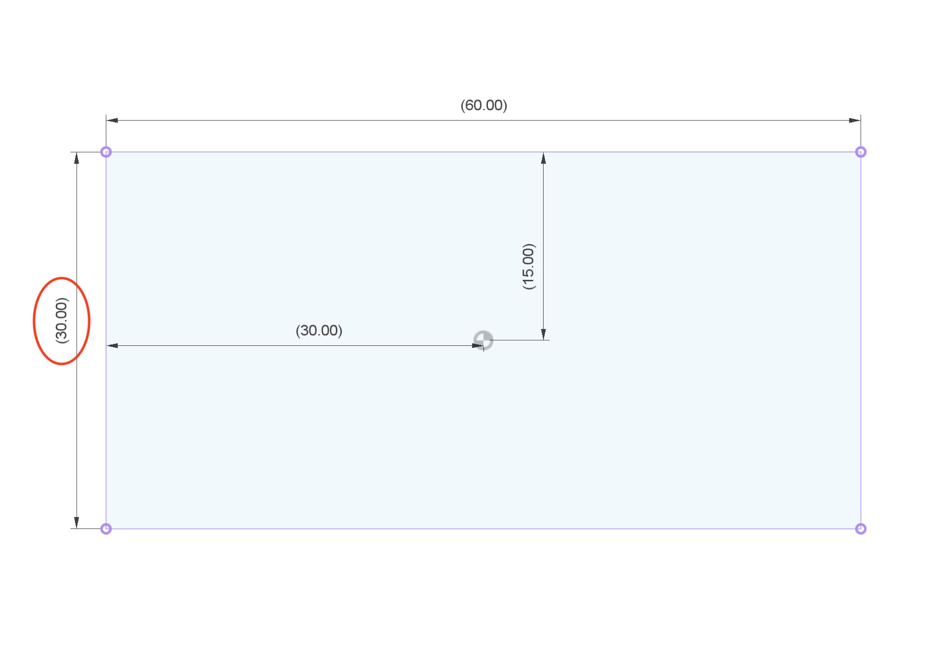
# 2 x 1 Rectangle
TIP
Construction lines and a midpoint constraint are key for this to work
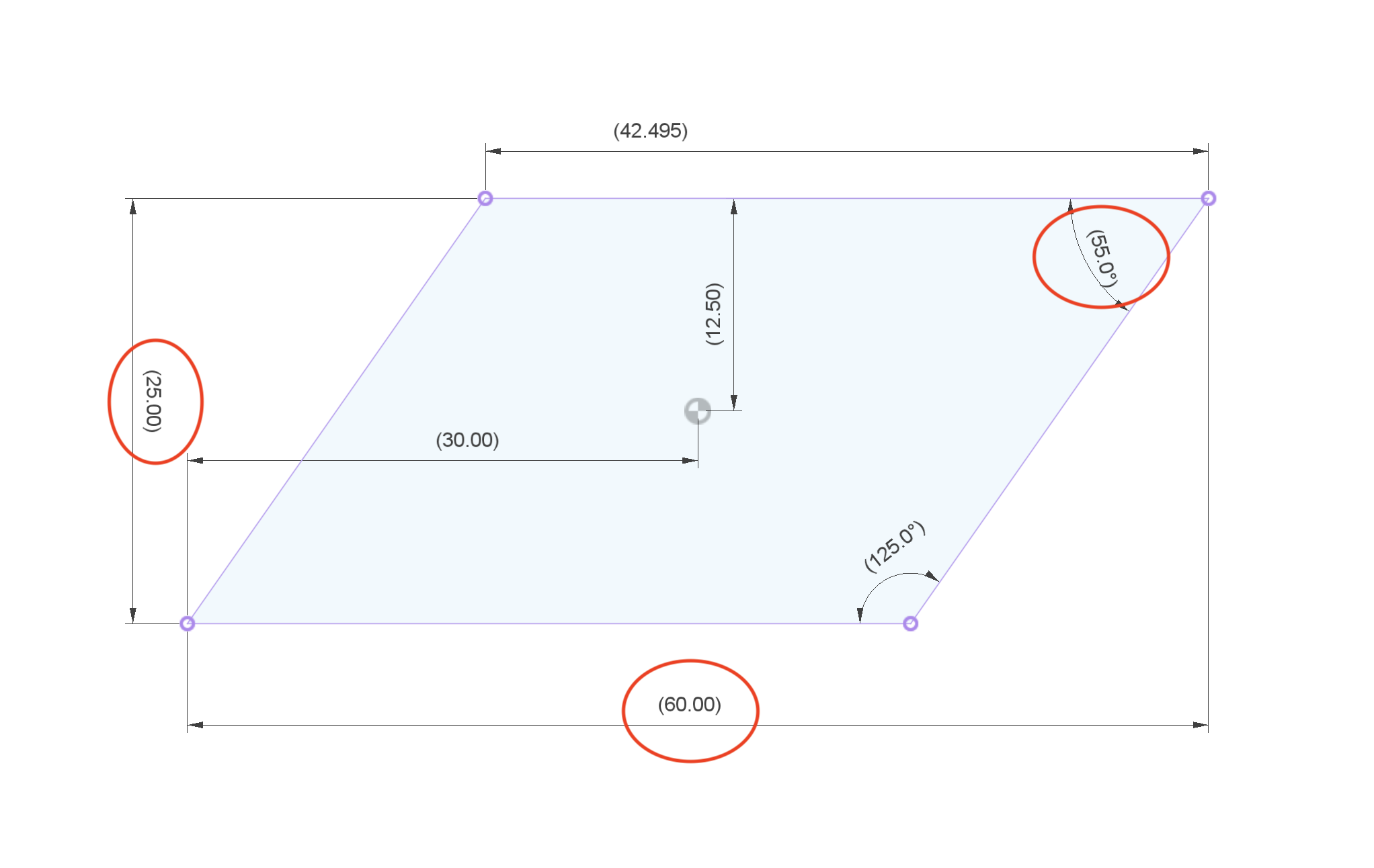
# Parallelogram
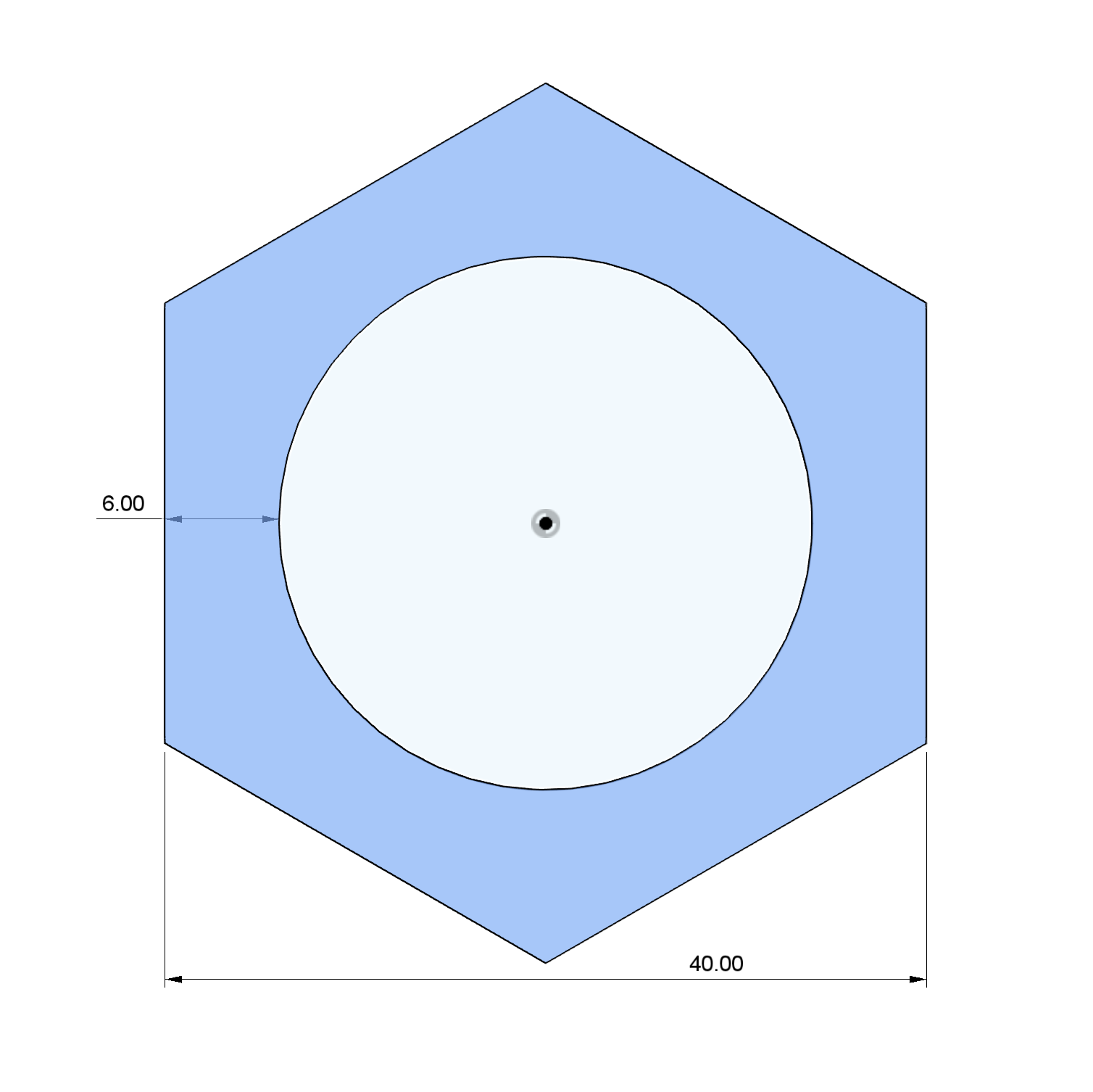
# Hex
TIP
Polygon tools are useful. In Fusion, right-click on the dimension tool to toggle dimensioning from a circle tangent to a circle center
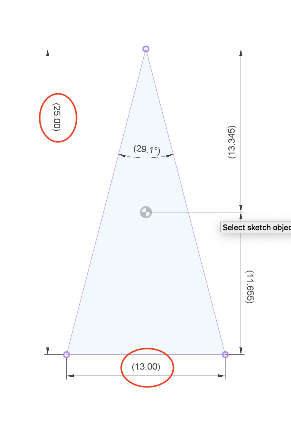
# Isosceles Triangle
WARNING
Don't forget to locate the triangle's center on the origin
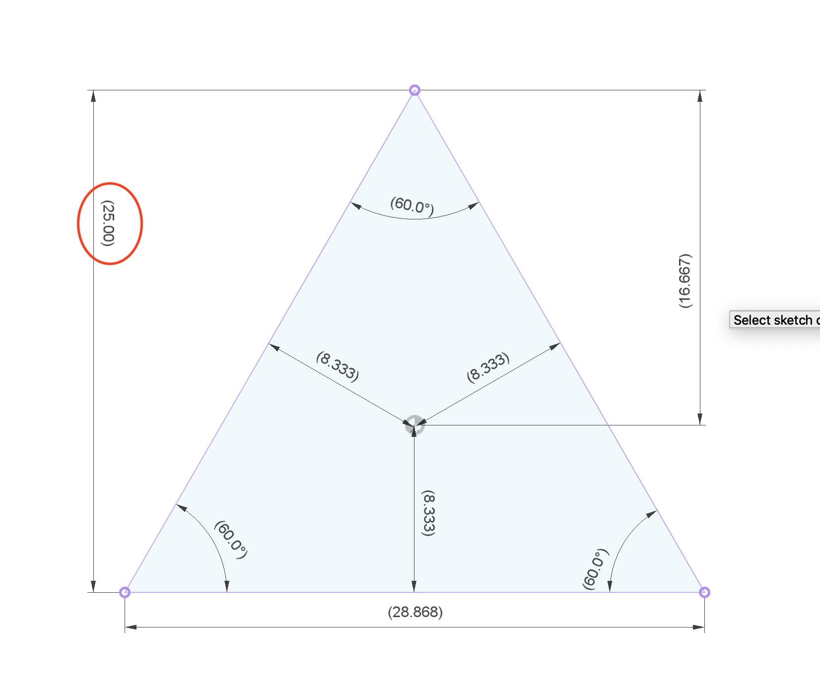
# Equilateral Triangle
WARNING
This should be controlled by just one dimension, and centered on the origin
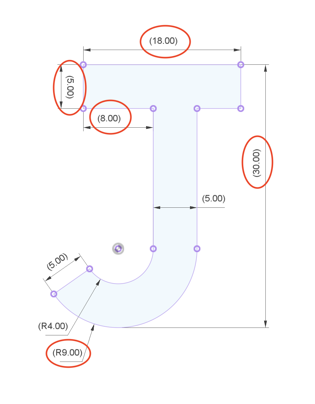
# Letter 'J'
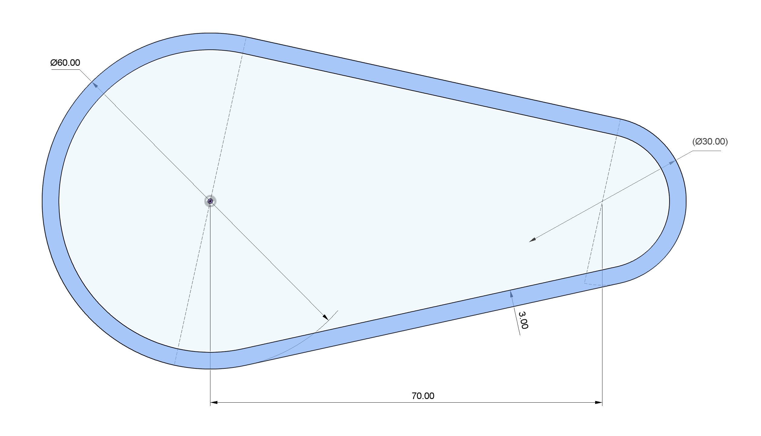
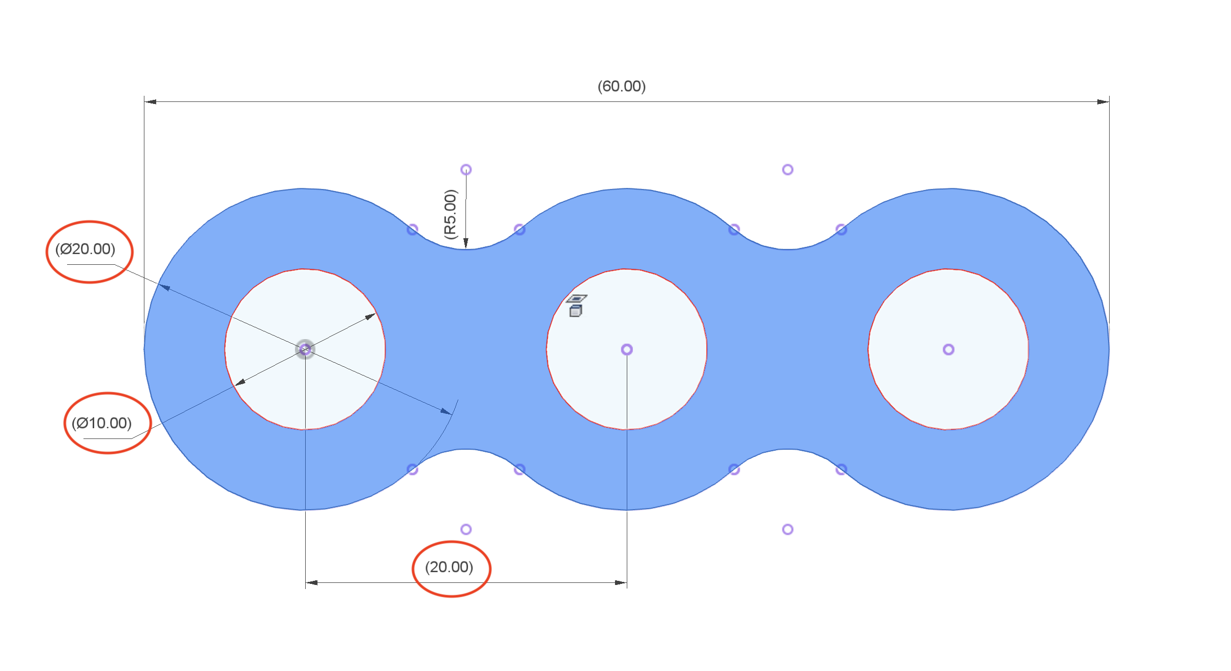
# Belt Profile
TIP
The Offset tool is very helpful here
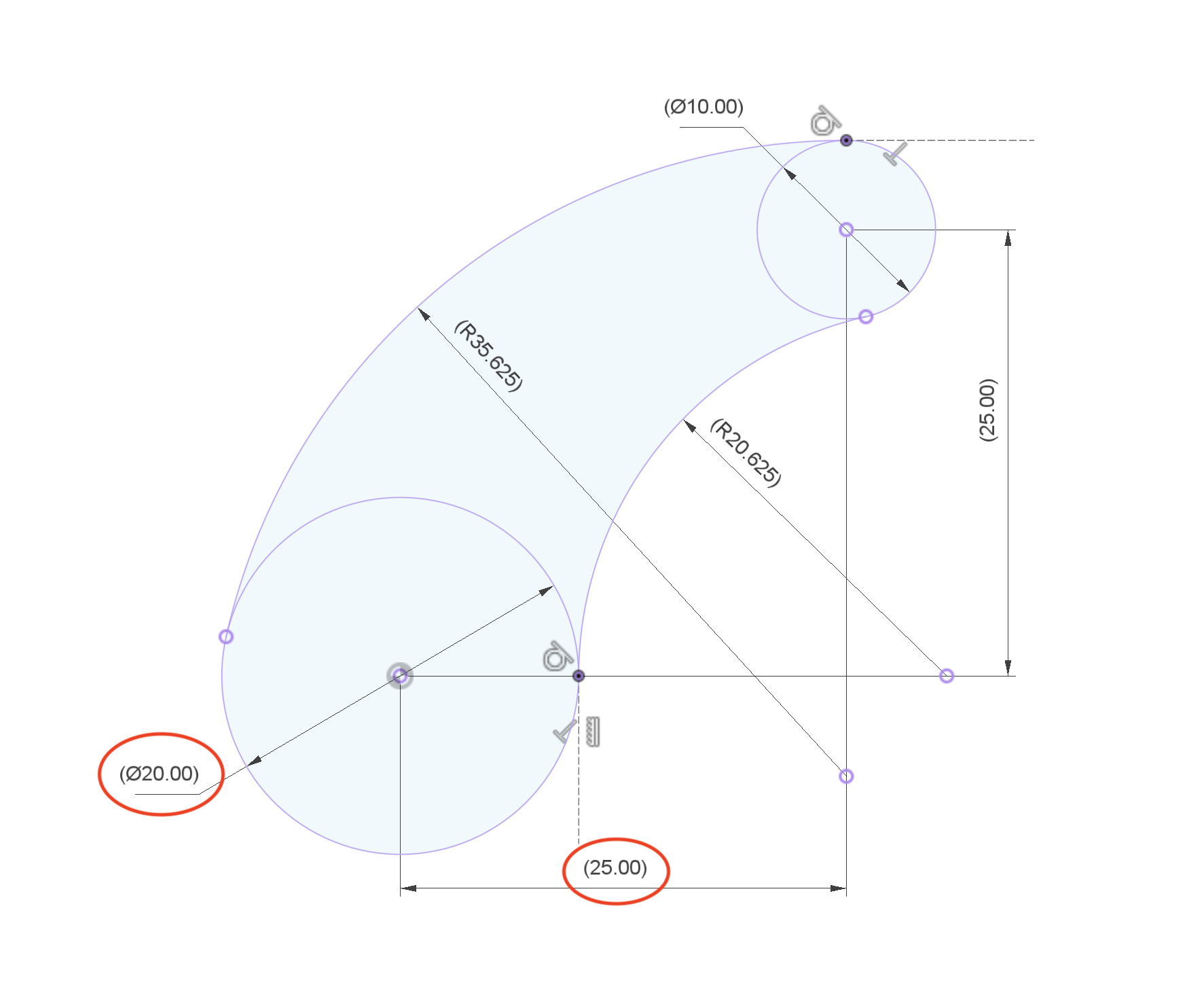
# Tangent Arm
WARNING
Note the 2 construction lines in this sketch. Curves should not only be tangent to one another at their end points, but also the horizontal & vertical lines. Tangency is critical in this sketch
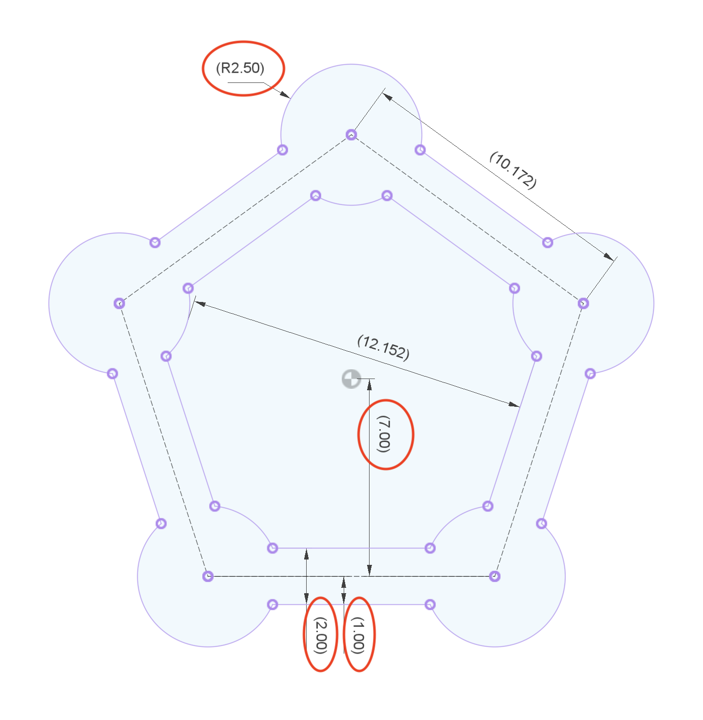
# Pentagon Towers Plan
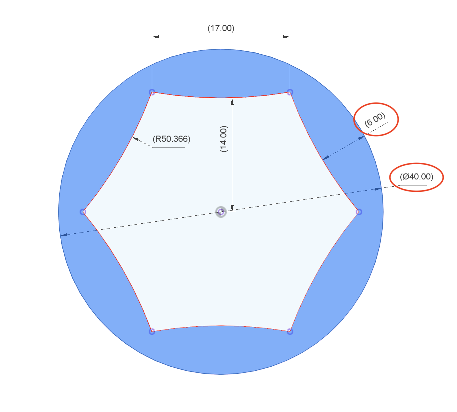
# Torx Profile
TIP
Note that this is controlled by just 2 dimensions. Building a useful set of constraints and using construction geometry is key
# Valve Cover Profile
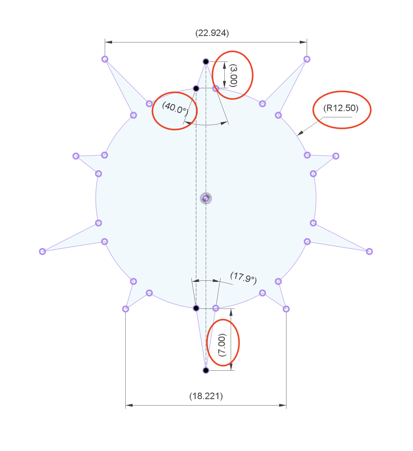
# Sunburst
BONUS
Try to control the number of points with a single parameter